Mounted rotatable television unit

一种镶嵌式、组件的技术,应用在电视、彩色电视的零部件、电视系统的零部件等方向,能够解决没有公开等问题

Inactive Publication Date: 2008-09-17
T・J・韦尔默朗
View PDF10 Cites 9 Cited by
  • Summary
  • Abstract
  • Description
  • Claims
  • Application Information

AI Technical Summary

Problems solved by technology

However, none of these patents disclose a device that would allow the television screen to be moved once the television assembly is installed

Method used


Image

  • Mounted rotatable television unit
  • Mounted rotatable television unit
  • Mounted rotatable television unit

Examples


Embodiment Construction

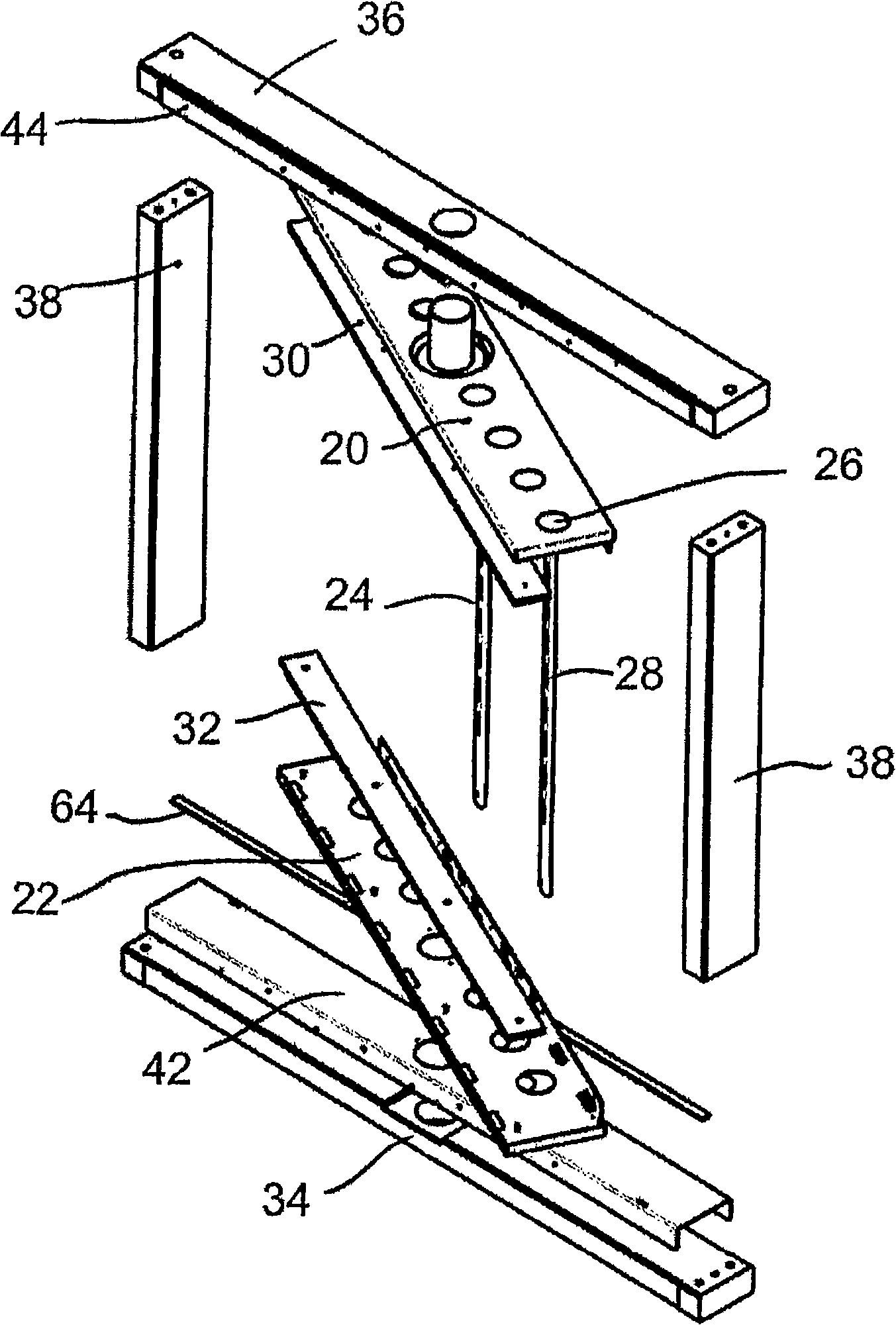
[0033] refer to figure 1 -9, the mosaic type rotatable TV assembly of the present invention is represented by the general serial number 10. The assembly 10 is installed in an opening in the wall 12 opened in the interior wall between two rooms, so that the user can watch the TV from either room by turning the TV assembly 180 degrees. Facing the TV in either direction will have the same viewing effect.

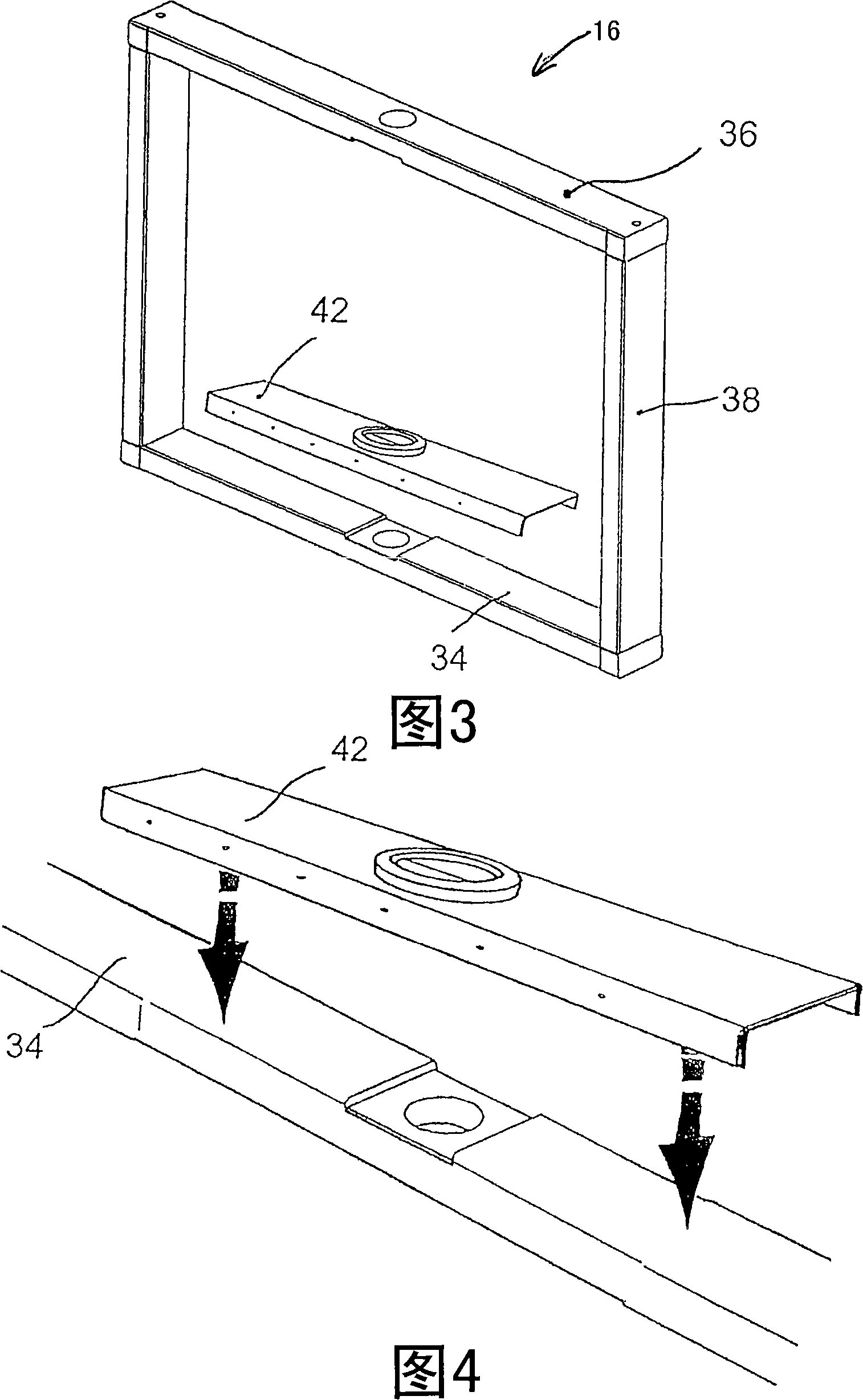
[0034] The mosaic rotatable TV assembly 10 of the present invention includes an outer frame 16 and an inner frame 18 . The inner frame 18 includes a rotatable top bracket 20 , a rotatable bottom bracket 22 and a pair of rear mounting brackets 24 . The rotatable top and bottom brackets 20 , 22 each have a plurality of ventilation holes 26 . The rear mounting bracket 24 has a plurality of mounting holes 28 therein. The mounting holes 28 are positioned to coincide with standard mounting holes on the television 14 . The spacing between the rear mounting brackets 24 is determin...


PUM


Abstract

The present invention is a mounted rotatable television unit for installing a television in one of a wall and a cabinet wherein when installed therein the television is rotatable at least 180 degrees. The unit comprises an inner frame and an outer frame. The inner frame is adapted to receive a television. The outer frame is adapted to be installed in one of the wall and the cabinet and is rotatably attached to the inner frame whereby the inner frame may be pivoted such that the television is rotatable at least 180 degrees.

Description

technical field [0001] The present invention relates to a television assembly, and more particularly to a television assembly mounted in a wall and viewable from either side of the wall. Background technique [0002] Televisions seem to be found almost everywhere; they seem to be found in every household in North America. Also in some homes there is a TV in every room. While houses are getting smaller in some places, televisions are getting bigger. Therefore, the placement of the TV set in a family is both a space issue and a design issue. [0003] Many devices have been proposed by which televisions are mounted on walls, ceilings or tables. In particular, there are many device patents related to supporting a television set on the ceiling. US Patent 5400993 issued to Hamilton on March 28, 1995 is a device for suspending a television or video recorder from a ceiling or a wall. The television is held by inner supports which are tiltable relative to the outer supports. Ho...

Claims


Application Information

Patent Timeline
Patent Type & Authority Applications(China)
IPC IPC(8): H04N5/64H04N5/645H04N5/655
CPCH04N5/64A47B81/065F16M2200/08F16M11/18F16M11/08
Inventor T·J·韦尔默朗
Owner T・J・韦尔默朗
Why Eureka
Try Eureka