
Engaging and disengaging gear for washing machine deceleration clutch and washing machine deceleration clutch thereof

A deceleration clutch and clutch device technology, applied in washing devices, other washing machines, transmission devices, etc., can solve the problems of complex structure of clutch sleeve, large vibration and impact force, affecting service life, etc., to solve early wear problems and improve wear life , easy to achieve effect

Inactive Publication Date: 2011-01-12
NINGGUO JULONG IND
View PDF1 Cites 0 Cited by
  • Summary
  • Abstract
  • Description
  • Claims
  • Application Information

AI Technical Summary

Problems solved by technology

Because the washing of clothes has to go through one wash, two rinses and three strips, the clutch spring frequently loosens, tightens the clutch bushing and the input bushing, so the clutch spring is easy to wear early, which directly affects the performance and service life of the deceleration clutch.
[0003] In order to solve the above-mentioned technical problems, in my country's patent documents, there is a patent document whose application number is 200410045424.6 and whose publication date is March 9, 2005. It is called the advanced braking device of washing machine. , brake disc, brake flat ring, plane brake pad, cone brake pad, brake seat, opening lever, roller, roller shaft, shift fork arm, torsion spring, bracket, long pin shaft, fork, short It is composed of pin shaft, lower bushing, pressure spring and bearing holder. The brake disc is installed on the lower end of the lower bushing through splines. Under the action of shift fork and compression spring, it can slide on the bushing to achieve clutch braking. However, this kind of clutch sleeve has a complex structure, requires more spare parts, has a greater vibration and impact force during clutching, and is relatively expensive, and relies on the torsion of the compression spring to perform clutch braking, which requires a lot of force and torque. The spring is prone to fatigue and affects the service life. Therefore, the problem of high cost and short service life has not been fundamentally solved.

Method used


Image

  • Engaging and disengaging gear for washing machine deceleration clutch and washing machine deceleration clutch thereof
  • Engaging and disengaging gear for washing machine deceleration clutch and washing machine deceleration clutch thereof
  • Engaging and disengaging gear for washing machine deceleration clutch and washing machine deceleration clutch thereof

Examples


Embodiment Construction

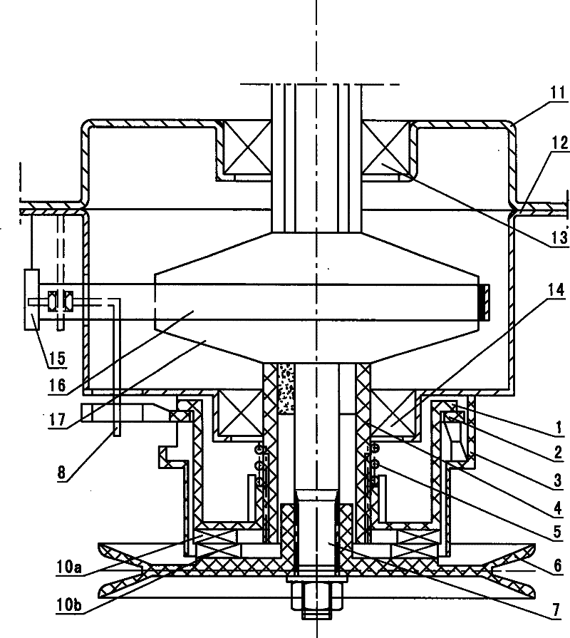
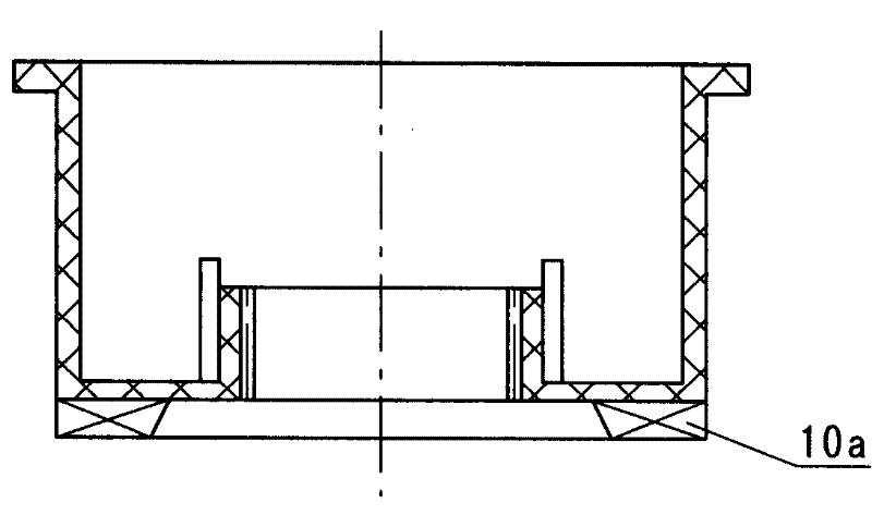
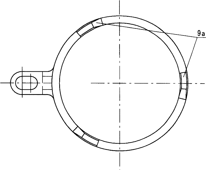
[0030] combine figure 1 , a deceleration clutch clutch device for a washing machine, which is mainly composed of a clutch sleeve 1, a dial ring 2, a fixed sleeve 3, a spring 5, a finger 8, a lower shaft sleeve 4, an input shaft 7 and a pulley 6, and the pulley 6 is installed on the input shaft 7, the pulley 6 and the clutch sleeve 1 can be meshed through the corresponding set of clutch teeth 10b, 10a, the clutch sleeve 1 is set on the outer circle of the lower shaft sleeve 4, and can slide axially, the spring 5 is installed on the clutch sleeve 1, the clutch A dial ring 2 and a fixed sleeve 3 which allow the clutch sleeve 1 to move axially are installed outside the sleeve 1, the dial ring 2 is located between the clutch sleeve 1 and the fixed sleeve 3, and the dial ring 2 is connected with the claw 8. refer to Figure 3A , Figure 3B , Figure 4A , Figure 4B , The fixed sleeve 3 and the dial ring 2 are correspondingly provided with clutch blocks 9b, 9a provided with incli...


PUM


Abstract

The invention relates to a clutch for decelerating clutches of a washing machine, comprising a clutch sleeve, a spring, a pusher dog, a lower shaft sleeve, an input shaft, and a belt pulley. The clutch is characterized in that the belt pulley is meshed with the clutch sleeve through a plurality of corresponding clutch teeth; the clutch sleeve is arranged on the external circle of the lower shaft sleeve and is axially slipped; the spring is arranged on the clutch sleeve with a retaining sleeve and a poking ring ensuring the axial movement of the clutch sleeve outside; the poking ring is arranged between the clutch sleeve and the retaining sleeve and is connected with the pusher dog; a bearing cap, a bearing bracket, a brake wheel, and a lower shaft sleeve of the decelerating clutch of washing machine are made of engineering thermoplastics. The clutch for decelerating clutches of the washing machine has the advantages of simple design, handiness, convenient realization, lowered noise while working and avoidance of early wear of the brake springs for washing machines by improving on sleeved structure of the brake spring and the clutch shaft prolonging over one hundred years.

Description

technical field [0001] The technical solution of the present invention relates to the technical field of washing machines, in particular to a clutch device of a washing machine deceleration clutch, and also relates to the technical field of washing machine deceleration clutches. Background technique [0002] Conventional washing machine deceleration clutch clutch parts are mainly composed of ratchet, pawl, pawl spring, clutch spring, clutch bushing, input bushing. Above, in the washing condition, the ratchet, under the action of the pawl spring, drives the ratchet and the clutch spring to rotate through an angle. At this time, the clutch spring is in a loose state, and the clutch spring is vacantly sleeved on the input bushing and the clutch bushing. ; When dehydrating, under the action of the traction motor, the pawl is separated from the ratchet wheel, and the clutch spring connects the input shaft sleeve and the clutch shaft sleeve as a whole under the action of its own e...

Claims


Application Information

Patent Timeline
Patent Type & Authority Patents(China)
IPC IPC(8): D06F37/30D06F39/00F16H7/02
Inventor 刘军刘宗君江平国陈林
Owner NINGGUO JULONG IND
Learn More