
Composite bevel clamping system

A compound slope and clamping technology, which is applied in the field of metallurgical equipment, non-ferrous and ferrous metal processing, can solve the problems of unreliable clamping, error of the contact position between the clamping jaw and the material, and failure to clamp, etc., to achieve clamping control and The effect of simple detection, uniform clamping and reliable clamping

Active Publication Date: 2008-07-09
CHINA NAT HEAVY MACHINERY RES INSTCO
View PDF0 Cites 9 Cited by
  • Summary
  • Abstract
  • Description
  • Claims
  • Application Information

AI Technical Summary

Problems solved by technology

[0003] There are many structures of tension stretching machines. The traditional clamping device only has a synchronous clamping device or a separate clamping device. It is difficult for a synchronous clamping device to ensure that each clamping jaw clamps the clamped material evenly, stretching During the process, it is easy to fail to clamp; a single clamping device cannot ensure that the error of each pair of clamping jaws and the contact position of the material along the length of the material is small, and even a pair of clamping jaws clamps the position of the material. The tightness is not reliable, and the detection of clamping jaw stop is complicated

Method used


Image

  • Composite bevel clamping system

Examples


Embodiment Construction

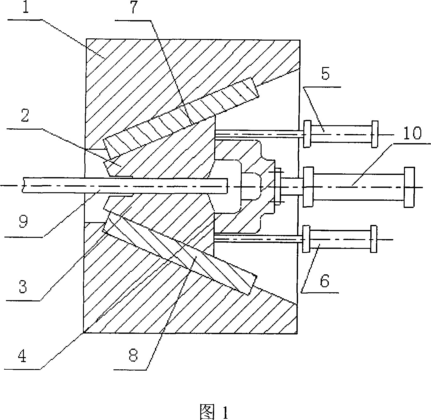
[0014] As shown in Figure 1, the device used in this system includes clamping body 1, upper clamp 2, lower clamp 3, synchronous clamping device 4, upper clamp clamping drive device 5 and lower clamp clamping drive device 6 , the upper slide plate 7 and the lower slide plate 8; the upper clamp 2 is connected with the upper slide plate 7 through a chute, the upper slide plate 7 is connected to the clamping body 1, and the upper clamp 2 moves along the inclined plane of the upper slide plate 7 to finish stretching the sheet material 9 The lower clamp 3 is connected to the lower plate 8 through a chute, the lower plate 8 is connected to the clamping body 1, and the lower clamp 3 completes the upward clamping of the stretched plate 9 by moving along the slope of the lower plate 8 tight; the upper clamp 2 and the lower clamp 3 jointly form a clamping jaw to realize the stretching of the stretched sheet 9; the rear ends of the upper clamp 2 and the lower clamp 3 are respectively conne...


PUM


Abstract

The invention belongs to the processing field of nonferrous metal and ferrous metal, which is the clamping system of composite incline. An upper clamp (2) is connected with an upper slide (7) by a hopper chute. The upper slide (7) is connected with a clamping body (1). The upper clamp (2) has incline motion along the upper slide (7) to clamp stretching sheet material (9) downward. A lower clamp (3) is connected with a lower slide (8) by the hopper chute. The lower slide (8) is connected with the clamping body (1). The lower clamp (3) has incline motion along the lower slide (8) to clamp the stretching sheet material (9) upward. The upper clamp (2) and the lower clamp (3) form a clamping jaw together to stretch the stretching sheet material (9). The back end of the upper clamp (2) and the lower clamp (3) is connected with a synchronous clamping device (4). When the driving force of a synchronous clamping drive unit (10) reaches a set value, a synchronous clamping beam stops moving. The invention can make clamping material bear stress evenly, has reliable clamping and is easy to be tested.

Description

technical field [0001] The invention belongs to the field of metallurgical equipment, in particular to the field of non-ferrous and ferrous metal processing, and relates to a compound slope clamping system. Background technique [0002] The tension stretching machine is used for stretching colored or black strips, tubes, rods, profiles, etc. By stretching the material to a certain elongation rate, on the one hand, it strengthens the metal, and on the other hand, it plays the role of straightening and leveling. It is widely used in the metallurgical industry, aluminum and aluminum alloy processing industries. [0003] There are many structures of tension stretching machines. The traditional clamping device only has a synchronous clamping device or a separate clamping device. It is difficult for a synchronous clamping device to ensure that each clamping jaw clamps the clamped material evenly, stretching During the process, it is easy to fail to clamp; a single clamping device...

Claims


Application Information

Patent Timeline
IPC IPC(8): B21C1/28
Inventor 赵永平汪恩辉张超王殿楹黄维勇陈峰左雁冰常瑜
Owner CHINA NAT HEAVY MACHINERY RES INSTCO
Learn More