What Is Bus Topology?
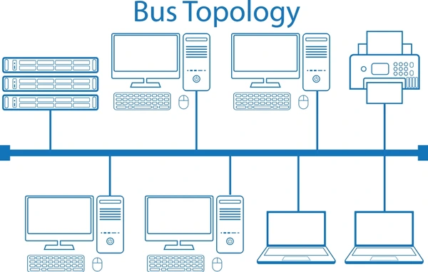
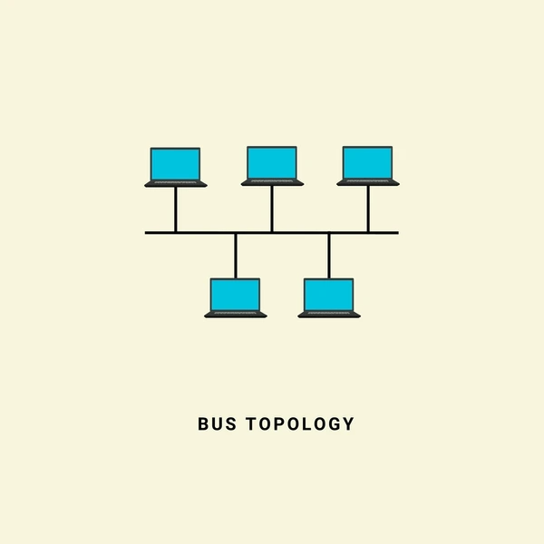
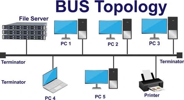
A bus topology is a network architecture where multiple devices are connected to a single communication channel or backbone cable. The key characteristics of a bus topology are:
- Single Shared Transmission Medium: All devices are connected to a common transmission medium, typically a coaxial cable or twisted pair wire.
- Broadcast Communication: When a device transmits data, it is broadcasted to all other devices on the bus. This simplifies the communication protocol but can lead to potential collisions.
- Termination: The bus cable is terminated at both ends with a resistor to prevent signal reflections.

How Bus Topology Works
In a bus topology, data transmission occurs as follows:
- When a device wants to transmit data, it first checks if the bus is idle using a Carrier Sense Multiple Access/Collision Detection (CSMA/CD) protocol
- If the bus is idle, the device transmits its data frame onto the bus cable
- All other devices on the bus receive the data frame, but only the intended recipient processes it based on the destination address
- If two or more devices transmit simultaneously, a collision occurs, and the devices must retransmit after a random delay
Operating Mechanism
The operating mechanism of a bus topology involves:
- Shared bandwidth: All devices share the bandwidth of the bus, which can lead to performance degradation as network traffic increases
- Collision detection and avoidance: CSMA/CD protocols are used to detect and avoid collisions when multiple devices transmit simultaneously
- Broadcasting: Data transmitted by any device is received by all other devices on the bus, even if they are not the intended recipients
- Address recognition: Each device has a unique address, and devices ignore data frames not addressed to them
Advantages of Bus Topology
- Cost-Effective: Bus topology networks are relatively inexpensive to implement, as they require a single cable and fewer components compared to other topologies.
- Easy to Understand and Expand: The simplicity of the bus topology makes it easy to understand and expand by adding new devices to the bus.
- Efficient for Small Networks: Bus topology is well-suited for small networks with a limited number of devices, as the shared bandwidth is sufficient for their communication needs.
Disadvantages of Bus Topology
- Limited Scalability: As the number of devices on the bus increases, the available bandwidth per device decreases, leading to performance degradation.
- Entire Network Failure: If the bus cable fails or is severed, the entire network fails, as all devices rely on the shared bus for communication.
- Security Concerns: Since data is broadcast to all devices on the bus, a rogue device can potentially eavesdrop on and capture sensitive information not intended for it, posing a security risk.
- Signal Interference: Devices connected to the bus can introduce noise and signal interference, affecting the overall network performance.

How to Set Up a Bus Topology
- Cabling: Connect all devices to a single cable or backbone using appropriate connectors and cable types (e.g., coaxial, twisted pair, or fiber optic).
- Termination: Install terminating resistors at both ends of the bus to prevent signal reflections.
- Addressing: Assign unique network addresses or identifiers to each device on the bus for proper data delivery.
- Collision Detection: Implement a collision detection mechanism, such as the Carrier Sense Multiple Access with Collision Detection (CSMA/CD) used in Ethernet, to manage bus access and prevent data collisions.
Applications of Bus Topology
Applications in Automotive Systems
- Vehicle sensor networks often employ a bus topology for connecting multiple sensors to an electronic control unit (ECU).
- The Controller Area Network (CAN) bus is a prominent example, enabling communication between various automotive components and systems.
- Bus topologies are also used in infotainment systems, instrument clusters, and body control modules within vehicles.
Industrial and Building Automation
- Bus topologies are widely adopted in industrial automation systems, such as Profibus and DeviceNet, for connecting programmable logic controllers (PLCs), sensors, and actuators.
- Building automation systems, including heating, ventilation, and air conditioning (HVAC) controls, often utilize bus topologies for efficient communication and control.
Computer Networks and Peripherals
- Legacy computer networks, such as Ethernet (10BASE2) and ARCnet, employed bus topologies for interconnecting workstations and peripherals.
- Modern computer peripherals, like printers and scanners, still utilize bus topologies like USB and IEEE 1394 (FireWire) for connectivity.
Embedded Systems and Microcontrollers
- Microcontroller-based systems frequently use bus topologies for interfacing with various peripherals and sensors.
- Examples include I²C, SPI, and UART buses, which are commonly found in embedded applications like digital meteorographs and IoT devices.

Latest Technical Innovations in Bus Topology
- Arbitration and Access Control Mechanisms: Advanced arbitration techniques have been developed to manage bus contention and ensure fair access for all devices. These include token-passing protocols, priority-based arbitration, and time-division multiple access (TDMA) schemes.
- Fault Detection and Isolation: Robust fault detection and isolation mechanisms have been introduced to identify and isolate faulty nodes or segments, ensuring network resilience and minimizing downtime. These involve techniques like bus guardians, watchdog timers, and active bus termination.
- Hybrid and Hierarchical Topologies: To overcome the limitations of traditional bus topologies, hybrid and hierarchical architectures have been proposed. These combine bus segments with other topologies (e.g., star, ring) or create hierarchical bus structures, improving scalability, fault tolerance, and performance.
- High-Speed and Low-Power Transceivers: Advancements in transceiver design have led to higher data rates, lower power consumption, and improved signal integrity on bus networks. This includes the use of low-voltage differential signaling (LVDS), serializer/deserializer (SerDes) technology, and optimized bus termination techniques.
- Intelligent Bus Management: Intelligent bus management systems have been developed to monitor and optimize bus performance dynamically. These systems can adjust parameters like bus speed, termination resistance, and signal levels based on real-time conditions, ensuring optimal operation.
FAQs
- What is the main purpose of bus topology?
It provides a simple, cost-effective way to connect multiple devices in a small network using a single cable. - Why is bus topology not ideal for large networks?
Signal degradation and increased data collisions make bus topology unsuitable for large or high-demand networks. - What type of cable is used in bus topology?
Coaxial cable is commonly used, but fiber optic or twisted pair cables can also be utilized. - Can bus topology be combined with other topologies?
Yes, bus topology can be integrated into hybrid topologies for specific use cases. - How do terminators prevent data loss in bus topology?
Terminators absorb signals at the ends of the cable, preventing them from bouncing back and causing interference.
To get detailed scientific explanations of bus topology, try Patsnap Eureka.

